Valves
A valve is a node element that opens, throttles, or closes to satisfy a condition you specify. The following valve types are available in HAMMER CONNECT:
| Valve Type | Description |
|---|---|
| Pressure Reducing Valve (PRV) | PRVs throttle to prevent the downstream hydraulic grade from exceeding a set value. If the downstream grade rises above the set value, the PRV will close. If the head upstream is lower than the valve setting, the valve will open fully. |
| Pressure Sustaining Valve (PSV) | A Pressure Sustaining Valve (PSV) is used to maintain a set pressure at a specific point in the pipe network. The valve can be in one of three states: partially opened (i.e., active) to maintain its pressure setting on its upstream side when the downstream pressure is below this value fully open if the downstream pressure is above the setting closed if the pressure on the downstream side exceeds that on the upstream side (i.e., reverse flow is not allowed). |
| Pressure Breaker Valve (PBV) | PBVs are used to force a specified pressure (head) drop across the valve. These valves do not automatically check flow and will actually boost the pressure in the direction of reverse flow to achieve a downstream grade that is lower than the upstream grade by a set amount. |
| Flow Control Valve (FCV) | FCVs are used to limit the maximum flow rate through the valve from upstream to downstream. FCVs do not limit the minimum flow rate or negative flow rate (flow from the To Pipe to the From Pipe). |
| Throttle Control Valve (TCV) | TCVs are used as controlled minor losses. A TCV is a valve that has a minor loss associated with it where the minor loss can change in magnitude according to the controls that are implemented for the valve. If you don’t know the headloss coefficient, you can also use the discharge coefficient, which will be automatically converted to an equivalent headloss coefficient in the program. To specify a discharge coefficient, change the Coefficient Type to Discharge Coefficient. |
| General Purpose Valve (GPV) | GPVs are used to model situations and devices where the flow-to-headloss relationship is specified by you rather than using the standard hydraulic formulas. GPVs can be used to represent reduced pressure backflow prevention (RPBP) valves, well draw-down behavior, and turbines. |
| Isolation Valves | Isolation Valves are used to model devices that can be set to allow or disallow flow through a pipe. Note that for Isolation valves, Left as referred to by the Is offset to the left of referenced link? property is left relative to the pipe's coordinate system (which is the alignment of the pipe), and not the absolute or world coordinate system. When an isolation valve is placed, a pipe bend is added at the location of the valve; that way if the pipe’s end node(s) are moved later the valve will remain attached to the pipe. If an isolation valve is closed, it will report N/A for HGL and Pressure results. |
Applying a Zone to a Valve
You can group elements together by any desired criteria through the use of zones. A Zone can contain any number of elements and can include a combination of any or all element types. For more information on zones and their use, see Zones.
To Apply a Previously Created Zone to a Valve:
- Select the valve in the Drawing View.
- In the Properties window, click the menu in the Zone field and select the zone you want.
Applying Minor Losses to a Valve
Valves can have an unlimited number of minor loss elements associated with them. Minor losses are used on pressure pipes and valves to model headlosses due to pipe fittings or obstructions to the flow.
If you have a single minor loss value for a valve, you can type it in the Minor Loss field of the Properties window. If you have multiple minor loss elements for a valve and would like to define a composite minor loss, or would like to use a predefined minor loss from the Minor Loss Engineering Library, access the Minor Losses dialog by clicking the ellipsis button in the Minor Losses field of the Properties window.
To Apply a Minor Loss to a Valve
- Select the valve in the Drawing View.
- In the Properties window, type the minor loss value in the Minor Loss field.
To Apply Composite Minor Losses to a Valve
- Click a valve in your model to display the Property Editor, or right-click a valve and select Properties from the shortcut menu.
- In the Physical: Minor Losses section of the Property Editor, set the Specify Local Minor Loss? value to False.
- Click the Ellipses (...) button next to the Minor Losses field.
- In the Minor Losses dialog box, each row in the table represents a single minor loss type and its associated headloss coefficient. For each row in the table, perform the following steps:
- Type the number of minor losses of the same type to be added to the composite minor loss for the valve in the Quantity column, then press the Tab key to move to the Minor Loss Coefficent column.Click the arrow button to select a previously defined Minor Loss, or click the Ellipses (...) button to display the Minor Loss Coefficients to define a new Minor Loss.
- When you are finished adding minor losses to the table, click Close. The composite minor loss coefficient for the minor loss collection appears in the Property Editor.
- Perform the following optional steps:
- To delete a row from the table, select the row label then click Delete.
- To view a report on the minor loss collection, click Report.
Defining Headloss Curves for GPVs
A General Purpose Valve (GPV) element can be used to model head loss vs. flow for devices that cannot be adequately modeled using either minor losses or one of the other control valve elements. Some examples of this would included reduced pressure backflow preventers (RPBP), compound meters, well draw down, turbines, heat exchangers, and in-line granular media or membrane filters.
To model a GPV, the user must define a head loss vs. flow curve. This is done by picking Component > GPV Head Loss Curve > New. The user would then fill in a table with points from the curve.
The user can create a library of these curve or read them from a library. Because there is so much variability in the equipment that can be modeled using GPVs, there is no default library.
Once the GPV head loss curve has been created, the user can place GPV elements like any other element. Once placed, the user assigns a head loss curve to the specific GPV using "General Purpose Head Loss Curve" in the property grid.
A GPV can also have an additional minor loss. To specify that, the user must provide a minor loss coefficient and the (effective) diameter of the valve.
A GPV does not act as a check valve. Flow can move in either direction through the valve. Therefore, when modeling a device like a RPBP, it may be necessary to place a check valve on one of the adjacent pipes to account for that behavior.
Note that minor losses do not apply to the following valve types: General Purpose Valve and Valve With Linear Area Change. These two valve types do not support a (fully) open status and always apply the head/flow relationship defined by their headloss curve and discharge coefficient respectively.
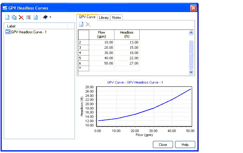
To Define a Headloss Curve
- Select the GPV in the Drawing View.
- In the Properties window, click the menu in the GPV Headloss Curve field and select Edit GPV Headloss Curves.
- In the GPV Headloss Curves dialog that appears, click the New button. Enter a name for the curve, or accept the default name.
- Define at least two points to describe a headloss curve. A point consists of a flow value for each headloss value in the Flow vs. Headloss table. The curve will be plotted in the curve display panel below the table.
- Click the Close button.
To Import a Predefined Headloss Curve From an Engineering Library
- Select the GPV in the Drawing View.
- In the Properties window, click the menu in the GPV Headloss Curve field and select Edit GPV Headloss Curves.
- In the GPV Headloss Curves dialog that appears, click the New button. Enter a name for the curve, or accept the default name.
- Click the Synchronization Options button and select Import From Library.
- In the Engineering Libraries dialog that appears, click the plus button to expand the GPV Headloss Curves Libraries node, then click the plus button to expand the node for the library you want to browse.
- Select the headloss curve entry you want to use and click the Select button.
- Click the Close button.